by Jorge R. Brotons-Mas, Manuel Valero and Liset Menendez de la Prida
Here we describe our procedures for implanting microdrives carrying multi-site silicon probes. We adopt similar approaches independently on whether a custom-made microdrive or the nDrive (Neuronexus) are being implanted, except otherwise noted. The pictures shown here were obtained from different sessions using different microdrive versions. All procedures meet the European directives and national regulations and they were approved by the corresponding committee of our institute.
Treatments and anesthesia: We initially use 5% isofluorane mixed in in oxygen (400-800 ml/min) for induction. Subsequent dose of isofluorane is maintained at 1.5-2% throughout surgery and physiological variables were continuously monitored with an oximeter (Starr Life Sci). Acute treatment included: enrofloxacin (10mg/kg, s.c.) and meloxicam (2.5mg/kg, s.c.) to prevent infection and inflammation, and the analgesic buprenorphine (0.05 mg/kg, s.c.).
Implanting plan: We carefully plan the implantation by considering the microdrive base dimension (Fig.1a, arrow indicates future location of probe implant). For the nDrive we also consider the dimensions of the cap (see below). We use several jewelers’ screws to facilitate posterior anchoring of the microdrive, with one or two screws for grounding and reference. Importantly, their location with respect to the craniotomy and the microdrive base should be carefully considered (Fig.1b). We apply any necessary modification to the microdrive base and the screws’ position at this point.

Figure 1
Microdrive preparation: Once we have tailored the microdrive base, we screw the base to the microdrive (nDrive only) and mount it onto the stereotaxic micromanipulator (Fig.1c). When we aim to target the dorsal hippocampus (2-3.5 mm depth), we choose to bring the silicon-probe tip well above the base to avoid potential breakage (Fig.1c, arrow). Hence, the probe depth is later adjusted with the microdrive itself (see below). We prepare the probe to protrude the base only if it is strictly necessary due to experimental requirements, as this results in challenging manipulation.
Microdrive implantation: We then prepare the craniotomy (by minimally breaking the dura). Next, we gently manipulate the microdrive assembly to target the craniotomy and to lower it till the base gently touches the skull (Fig.1d). We check probe position relative to the craniotomy and cement the microdrive base to the screws and the skull (Fig.1e). Extreme caution should be taken to avoid cementing any part of the microdrive machinery, nor the silicon probe and its connections. We avoid directly contacting the microdrive at this point till the cement is fully cured. Only then we carefully release the microdive from the stereotaxic manipulator.
Microdrive adjustment: First, we check microdrive anchoring and add more cement if required. Next, we gently turn the microdrive screw to advance the probe under visual control and check for penetration in the brain (typically about 500-800mm). We then cover the probe and the craniotomy with sterile Vaseline (Fig.2a). Depending on the experimental design we control penetration by simultaneously recording local field potentials while advancing the probe. If this were case, we previously have had connected the microdrive to the recording system using a dedicated stereotaxic manipulator adaptor.
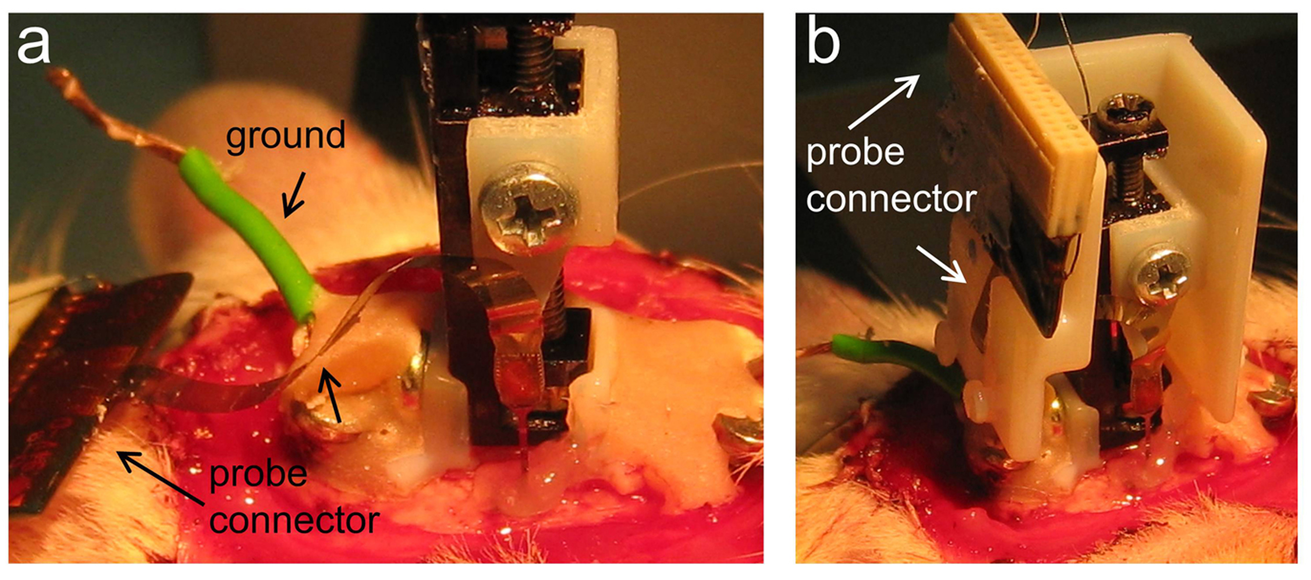
Figure 2
Microdrive cap (for nDrives only): In case of nDrive implantation, we then release the probe connector (Fig.2a indicated) and check for the cap position by making the necessary adjustments (not shown). Once the cap fits well at the desired location, we slightly cement it. Care should be taken that the flexible ribbon’s probe connector passes through the slot of the cap (Fig.2b). We recommend using one-side open caps to keep visual control of the probe. We also recommend gluing the probe connector to the cap and not to the skull. Next, we slightly cover the flexible ribbon with Vaseline before adding more cement to the cap while keeping visual control of the probe (Fig.3a, arrow). Once the one-side open cap is fully anchored, we add more Vaseline to protect the microdrive machinery and the probe before enclosing the cap (Fig.3b, arrow). Additional cement is applied if required.
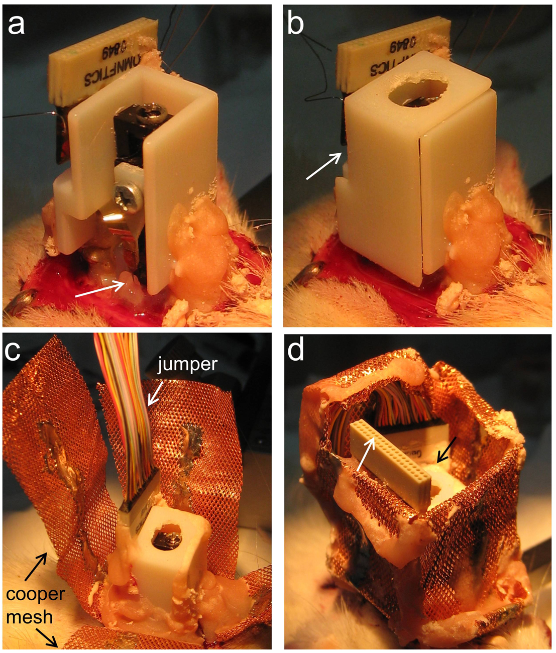
Figure 3
Microdrive electrical connection: Only once the microdrive (together with the cap in case of the nDrive) is fully anchored, we proceed with electrical connection by bonding the ground and reference probe wires to the corresponding skull wired screws. We next connect a jumper (Omnetics male-to female extension) to the microdrive connector (Fig.3c). We found this jumper essential to avoid mechanical forces to be transmitted to the microdrive while connecting and disconnecting the probe to the recording system (even if Neuronexus H-probes are being used). In most cases, we also use the jumper to check on the local field potential signal and readjusting the probe depth if required.
Copper mesh: When we implant our custom-made microdrive we use a copper mesh to protect the implant instead of a cap. We also use the copper mesh for the nDrive even if its cap was implanted, since this gives additional protection (Fig.3c). We ground the copper mesh and then accommodate the mesh folders so that both the jumper (Fig.3d, white arrow) and the microdrive screw (Fig.3d, black arrow) are protected and accessible. Then, we add more cement if required and control for bleeding. We carefully clean all cement derbies from the vibrissae. Finally, the area is dusted with topical antibiotic powder and surgery is terminated. We control for recovery, using glucosaline at different intervals and special care over the next days.
You can cite this post using this link: http://hippo-circuitlab.com/?p=54