By Manuel Valero and Liset Menendez de la Prida
In our previous post we described our general procedures for implanting microdrives carrying multi-site silicon probes. In general we use similar approaches to implant custom-made or commercially available microdrives. In the particular case of the dDrive from Neuronexus, there are some specific steps that are critical for a successful implantation and we detail those steps here. All procedures meet the European directive and national regulations for experimental research and they were approved by the ethics committee of our institute.
- Implanting plan: It is critical to plan the position of the dDrive cap with respect to the craniotomy (Fig.1a, arrow 1) and the rest of screws (arrows 3 and 4). Check there is room enough for the drive cover (arrow 2) since you will need to slightly adapt once everything is in place (Fig.1a, top view; Fig.1b, side view). Add additional bone screws if possible to ensure implant anchoring. Consider having an extra-taller screw to help anchoring the microdrive cap in subsequent steps.
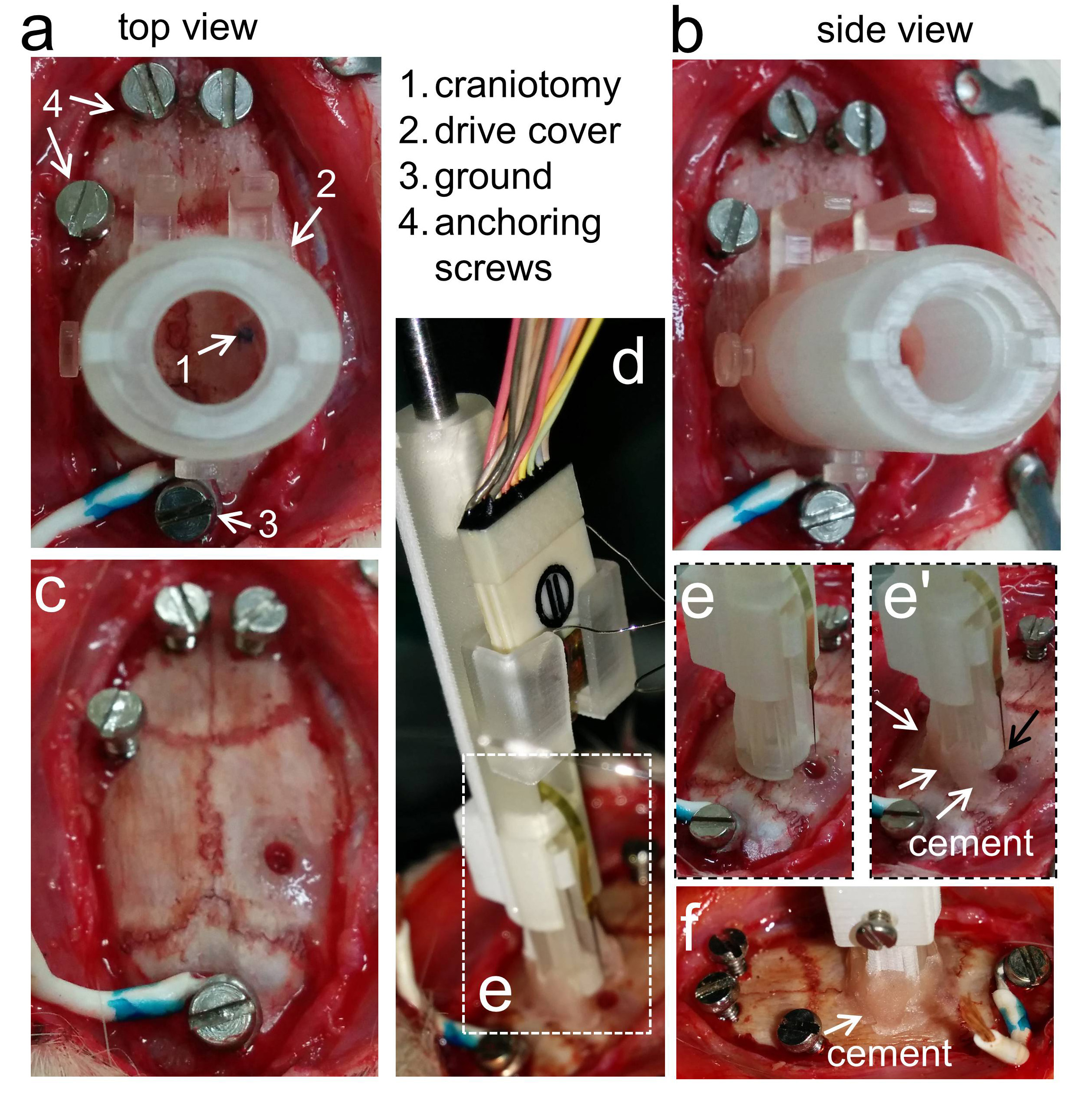
- Microdrive implantation: Then remove the drive cap to start implantation (Fig.1c). Use the connector holder to advance the microdrive being sure the probe is not exposed (Fig.1d). Note the microdrive is level with the skull (Fig.1e). Gently cement the back of the microdrive; be cautious not to cover the probe tip (Fig.1e’). See a back view at Fig.1f. Keep in mind the drive cover when adding dental cement at this point and avoid spreading it so much.
- Probe adjustment and electrophysiological confirmation: We typically adjust the probe depth during surgery and confirm desired position by electrophysiology. To this purpose first release the drive from the connector and disengage the connector carefully so that you don’t damage the probe (Fig.2a). We connect the probe to an amplifier using a jumper (Fig.2a, arrows) and gently advance the probe in place with a screwdriver (Fig.2b) while controlling electrophysiological signals (Fig.2c). We use typical electrophysiological hallmarks to guide penetration. These signatures would depend on the anesthesia used and the structure under study. Since we typically use isofluorane and target the dorsal hippocampus we rely on the following: (a) multi-unit activity from the CA1, CA3 and /or the granule cell layer of the dentate gyrus, (b) spontaneous dentate spikes with a typical reversal profile between layers. You can choose to leave the probe above the target region for subsequent refinement.
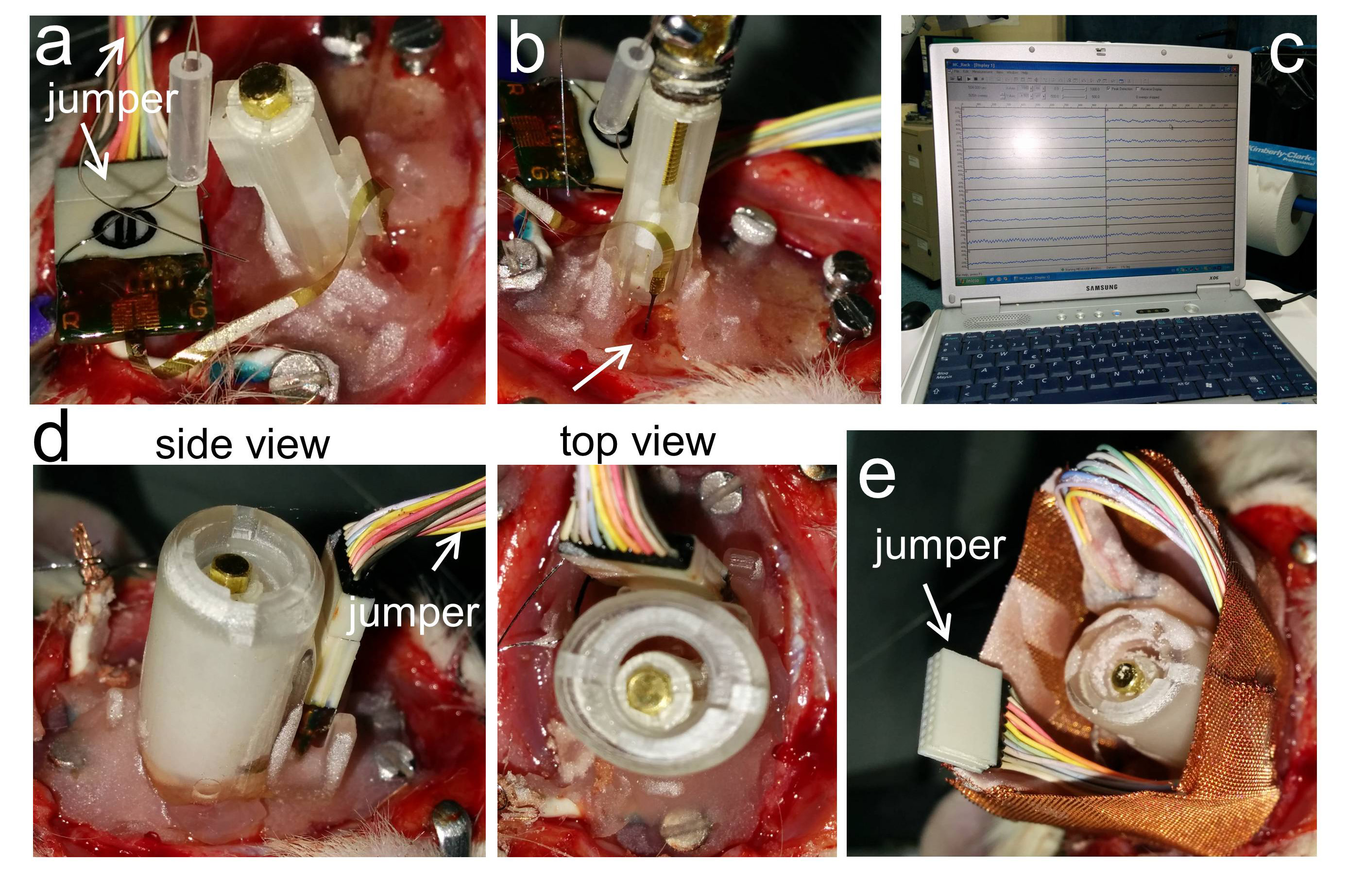
- Microdrive cap and copper mesh: Once the probe is at the desired position, cover the tip and the microdrive sensible parts with sterile Vaseline to protect all the system. Then install the cap and the probe connector in place and secure it with dental cement (Fig.2d). Be sure the probe is still recording once you are done. Cover all other screws with dental cement to secure the microdrive. Finally install the copper mesh around the microdrive as we described in our previous blog. Place the free end of the jumper at the mesh side to facilitate connection (Fig.2e).